Building the Model
Having gathered together a large number of books, photographs and
videos of the Woodhead route over the years, reference data was not hard to
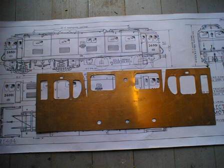
come by! As with previous modelling projects, the Skinley drawings (at
10mm:1ft scale), were used to give greater detail and more information on
critical dimensions.
An additional opportunity to gather more research data presented itself when I e-mailed an enquiry to the National Railway Museum at York seeking any internal cab photographs. An early response not only advised that there was much source material available in the readers' library, but they also sent a readers ticket plus an invitation to view, measure and photograph the interior of the the real thing, No. 26020 herself! I didn't need asking twice! The visit took place in September 2002, and I was given a very informed guide and spent a considerable amount of time learning more about the prototype and taking photographs inside the cabs.
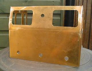
It was decided to start the project with the cab sections as these were, apart from the strangely profiled roof, probably the most esoteric feature of these locomotives. To try to keep the thickness of the windows as realistic as possible, 20swg brass sheet was used for the whole of the cab sections, and having cut them to size, all window and door apertures were cut out, and holes drilled for the headlights, handrails, end steps and tail-lamp brackets.
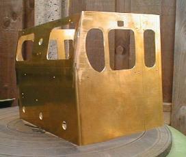
Each cab unit was then carefully bent up, including the slanting top section of the front, and the resultant 'box' soldered and filled where necessary with car body filler.
Details such as the tail-lamp brackets and step were made from scrap
metal and rivetted to the ends. One of the main visible features of the EM1 is
the rivetting; rows and rows of the things where the re-inforced steel plates
were joined - re-inforced as after the war, the Gorton works used materials
used in the production of military tanks to keep the build costs low! I have
never wanted to be classed as a 'rivet counter' so I can't say how many there
are ............ but undaunted, a start was made by marking out and punching
the main locations for the rows of rivets, drilling the holes 1/16" and then
got stuck in with hammer and cutters! Small brass brackets were made and
soldered to the inside of the cabs, level with the floor and at the top of the
sides. These were then used to bolt the completed cab units to the floor and
the main body bulkhead. Thin brass strip, (xxXxx), was bent carefully to shap
and soldered onto the main cab units to provide the prominent front window
surrounds and the drivers door frames.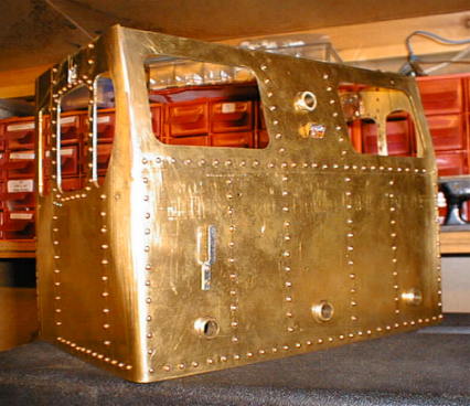
Cab Interior
The main control desk was formed from a single piece of .016thou
brass sheet using the photos from the NRM and a drawing from the NRM library
also obtained on my visit.
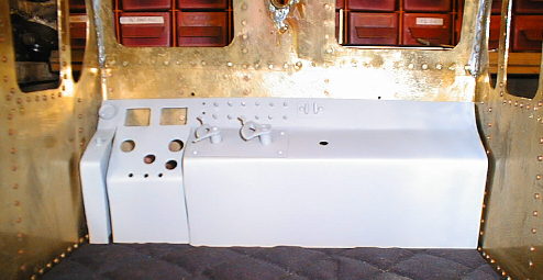 Suitable
holes and cut-outs were made and by raiding the scrap box plus several brass
screws, bits of 30amp fuse wire etc, a reasonable semblance of the controls was
made. The two main controls were built up from redundant wristwatch gears and
brass scrap. Finally, the various dials, meters and gauges were reduced on the
PC and then printed before glueing behind some clear acetate.
Suitable
holes and cut-outs were made and by raiding the scrap box plus several brass
screws, bits of 30amp fuse wire etc, a reasonable semblance of the controls was
made. The two main controls were built up from redundant wristwatch gears and
brass scrap. Finally, the various dials, meters and gauges were reduced on the
PC and then printed before glueing behind some clear acetate.
![]()
![]()